
What can you connect to the TX brick?
The fischertechnik TX brick provides 12 inputs and 8 outputs. From those 12 inputs, 8 are so called Universal inputs which can be software configured between analog and digital mode. 4 inputs are fast counters which also can be used as regular digital inputs. Inputs have two different modi which fischertechnik calls 10V mode and 5kΩ mode. The first measures voltage and the later measures resistance. The 8 Universal inputs can be configured analog or digital whereas digital mode is a software emulation. In analog mode, the OS writes an integer of the measured value, voltage or resistance, into a register. In digital mode, the OS writes a Boolean when a max threshold or a min threshold is reached. The threshold is hard coded and cannot be changed. There are different thresholds for reaching a logic 1 than opposed to reaching a logic 0 which is called a hysteresis. This avoids that an input constantly trips between two states if the input value is just around a certain threshold. The four counter inputs are different. They are directly connected to PIO pins on the processor and can be either driven by a regular CMOS or TTL signal or by pulling them to ground. Those ports are internally pulled high and in a way behave similar to the digital mode of the 5kΩ ports.
The 8 outputs are driven by a pair of MOSFETs through a PWM controller. The PWM controller can control the amount of energy released to the load such as the speed of a motor or the brightness of a light. Outputs can be paired to control polarity in software such as the spin direction of a motor.
Unique is the way how fischertechnik implemented port expansion. The TX brick can work in two different modi called Online and Offline mode. The Offline mode is what we would expect from a microcontroller: the app is downloaded to the brick and locally executed. In Online mode, the brick receives commands via either USB, Bluetooth, or RS485 interface. The expansion uses Online mode where the app is running locally on the master brick which remote controls other bricks via the RS485 interface in Online mode. Nine bricks can be daisy chained this way. From a programming perspective, this is somewhat easier than dealing with digital port expanders based on I2C or digital to analog mapping as more common in the Lego NXT world. The Lego brick, btw, has only 4 inputs and 3 outputs and I believe only one input is capable of reading analog values. The problem is mitigated in the Lego world via the I2C bus. The fischertechnik brick also features an I2C bus which finally received OS support in 2012. Though there are no fischertechnik native I2C sensors at this time, inexpensive industrial sensors can be easily connected. Since I2C support is new with fischertechnik, we are only starting to see models being introduced by the user community. (Check out Rei Vilo's I2C page.) Lego robotics models tend to feature more interesting sensors due to the benefit of early I2C support and the availability of I2C sensors from third parties with the same look-and-feel as Lego's native sensors, but have much less complexity than fischertechnik models due to the port count limitation. The fischertechnik brick can be much easier used for generic projects both due to port count and its open connectors. Lego uses proprietary connectors which are not just hard to come by but one also needs special tools to crimp cables which are not widely available.
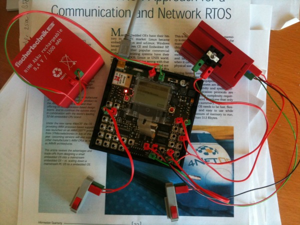
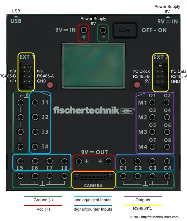 Connecting stuff to the TX brick is easy and intuitive. Inputs are on the left and the bottom and outputs are on the right. All ports are equipped to receive fischertechnik's 2.6 mm banana plugs which are kind of odd compared to the more typical 3 mm connectors used by model train people for instance or 4 mm lab connectors. Though, they are easy to get as spare parts (or eBay) for reasonable amount of money. There are conveniently placed ground connectors on the left and bottom and 9V connectors in the lower middle. 5V is provided via Ext 2 if required. Start by connecting 9V DC power either via the connector in the top middle or via the 3 mm power jack. You need a power source which can provide at least 1A, better 2.5A. fischertechnik recommends their Accu Set or the Power Set or Energy Set. (The Power Set contains an international switched power supply and the Energy Set contains a regional linear power supply.) A generic power supply should do as well.
All inputs can be activated in digital mode by bridging an input to ground which is perhaps the easiest way to connect a sensor to the TX brick. On the Universal inputs in digital 5kΩ mode and on the counter inputs in general, a bridge to ground counts as a logic 1. This is called negativ logic. This also works to some degree with analog components such as photo transistors or resistors if the threshold values are met. Universal inputs can also be configured in 10V mode. 10V mode measures voltage instead of resistance. In principal this is the same. If you wanted to use a resistive sensor, you could either connect it between 9V and input in 10V mode or between ground and input in 5kΩ mode. 10V mode could also directly be driven by TTL positive logic. (CMOS logic might be a stretch because of threshold values.) In analog mode, 10V mode would be a nice way to interface with other micro controllers or digital sensors where the message is translated into different values of voltage. The Universal inputs, those which can be configured analog or digital, are on the left and to the left bottom.
The counter inputs are to the right bottom. The placement of the counter inputs is not random. Encoder motors, those motors which have a built-in position sensor, like mice in the old days with a ball under it, utilize the counter inputs. As mentioned, the counter inputs can be used as regular digital inputs, they are in fact the only real digital inputs, but also as, what the names says, "counters". Those counters are different from the counter pins on the processor. Counter pins on the processor are frequency counters. Counter input interfaces are integer variables which count one up whenever a logic 1 is reached. So this is more a software concept then a hardware. Btw, from studying the PCB, it looks like that the counter inputs can also be theoretically configured as outputs but there is no software support for this as of now. The counter input are pulled up which counts as logic 0 - negative logic again. The counter inputs behave in a way similar to Universal digital inputs in 5kΩ mode as the pull up voltage is provided on the input, but which is here higher, 5V as opposed to 2V with the Universal. They do accept a standard TTL or CMOS signal, though.
The outputs are to the right. There are no direct ground connectors close by. All output ports are internally connected via two MOSFETs. The MOSFETs are connected to ground and to 9V with the output sitting in the middle. So either output can be pulled to ground or to Vcc per software command which is the way that motors can change their spin direction. If polarity change is desired, the load needs to be connected between a pair of output ports limiting the usable port count to 4 if 4 such motors are connected. Without polarity change, the load is connected between the output and ground, or alternatively to output and another unused output which is by default pulled to ground. With the later method, only four outputs would be useable as well. If spin direction does not matter, you can connect 8 motors between output and ground. The outputs are all protected from static discharge as well as short circuiting and are current limited. They are also protected from not having a load, something MOSFETs do not like normally and are only activated if a load is detected. The driver IC can work with many different loads which includes inductive loads such as motors, magnetic valves, electro magnets, incandescent light, and LEDs. Be careful doing something crazy such as connecting anything with a RC or LC filter such as used in the radio art. The driver goes bezerk as tested by the author. If you need to control something here, better use an optocoupler for isolation.
Supported but invisible is the Bluetooth interface. Multiple bricks can talk via Bluetooth to each other. Any device which maps a serial port to Bluetooth can send commands to the brick. The Bluetooth port is most often used when communicating between a PC and the brick in online mode. Online mode liberates the brick from resource constraints such as complex math models or large apps. Some software such as Microsoft Robotics Development Studio only work in online mode. Bluetooth is essentially an alternative to the USB port which is also a mapped serial port.
Besides inputs and outputs there are other connectors. Widely discussed in the fischertechnik community is the I2C port on the Ext 2 connector. I2C, stands for interface-to-chip, is a very common chip interface. Many industrial sensor chips have those interfaces directly on the chip. Adding a sensor is as easy as taking one of those inexpensive sensors and connecting it - from a hardware perspective. From a software perspective, I2C is very complex. Not so much on the protocol level, but more so on the application levels as many of those sensors chips have intelligence on their own little microcontrollers on board and come with application notes 100 pages long. I2C is a bus and you could connect input as well as output devices. While Lego for instance uses I2C for its ultrasonic distance sensor, fischertechnik apparently codes the values via some perhaps proprietary digital messaging format, operating a Universal port in digital 5kΩ mode. This method has the beautiful term "bit banging".
Also very noticable is the camera connector in the lower middle. fischertechnik added this probably because it is a native feature of the processor. The connector is directly connected to the processor's image sensor inputs. My guess is that fischertechnik wanted to future proof the brick without seriously thinking about an image sensor. Could be interesting, though, with image recognition software. The processor would be definitely fast enough for that - it is much faster than the more mature Lego NXT brick. There is nothing announced by fischertechnik and no library support for that connector as of now.
Last but not least, the Ext connectors are used to daisy chain bricks. Bricks talk to each other via the robust RS485 serial protocol.