
The TX Brick accepts a wide variety of Inputs
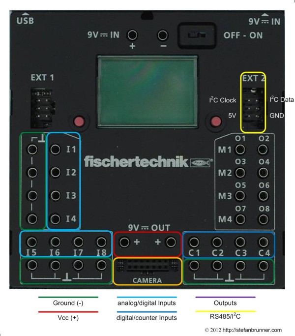
The fischertechnik ROBO TX Controller brick features various inputs: Universal inputs, counter inputs, camera input and I2C. From those, the Universal inputs are the most popular with the counter inputs reserved mostly for special tasks such as counting events or connecting encoder motors. There is no software support for either the camera input at the time. Technically, the USB, the Bluetooth, and the RS485 interface all count as inputs but driving them is more a protocol issue than a hardware one and for that reason not subject here. How stuff is physically connected to the brick was already described in the last section. Hence, I would like to focus here on the internals of those input connectors. When using fischertechnik's ROBO Pro in Level 1 with the instruction for their models, hooking up sensors is easy. But I would like to get a little deeper and explore how those ports really work from a hardware perspective. Once we know this, we can think about what else we can hook up to the brick.
Analog Inputs
The most popular inputs are the so called Universal inputs which can be configured in analog and digital mode. Internally, Universal inputs are always analog but this should be of no concern here. More interesting is that those ports, in analog or digital mode, work in two different modi which fischertechnik called the 10V mode and the 5kΩ. The difference between the two is that the first accept a positive voltage (up to 10V) on the input and the later a resistive load connected between the input and ground similar to the resistance setting on a multimeter. The software delivers for that either an integer with the voltage in millivolt or an integer with the resistance in Kiloohm. We will see in a minute that both are actually very similar concepts.
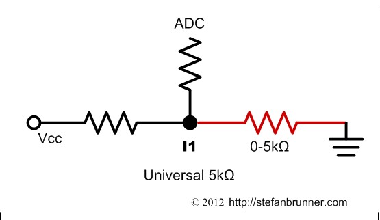
In 5kΩ mode, a voltage divider is built between ground and Vcc supply voltage with the help of a resistor. One resistor is internal and the second resistor is the sensor itself. The sensor is connected inbetween the input and ground. The internal resistor delivers about 2V to the input. Depending on the resistive value of the sensor, the analog/digital converter (ADC) measures a different voltage value according to Ohm's law. The ADC cannot measure resistance directly but only indirectly via voltage drop. The OS converts the voltage reading into a resistive value and writes that value into a register. The internal resistors are chosen in a way to limit any current to protect the sensor as well as conserve battery.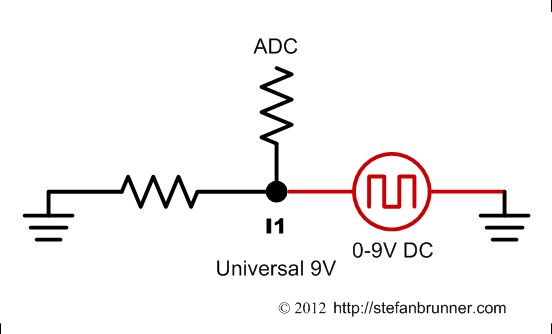 In 10V mode, the hardware configuration looks very similar. This time we do not need a voltage divider. The input is pulled to ground so that the input does not float. This is done with a resistor with sufficiently high value. When we connect a voltage source, the ADC directly samples the value and he OS writes it into a register where it can be read by our app.
The inputs are protected which does not make them highly sensitive. A voltage of at least 75 - 100mV needs to be applied to the input. This sounds like very little, but for some sensors such as thermo couples or touch sensors this is not low enough. Those would need an instrumentation amplifier to strengthen the signal sufficiently. Actually, The E-Tec module and even better the Darlington (Leistungsendstufe) from the Elektronik set of the 80s and the "Silberling" Grundbaustein (basic block) from the 70s would do that job nicely. Since inputs are multiplexed into the same ADC pin on the processor, there is a time lack when updating the register. Also values tend to dance around a bit, hence you never get the same exact value if you measure multiple times. This is irrelevant for sensors unless we use the TX brick to trace precise voltage levels. Precision is actually not that bad and lower than 5% as I measured.
On the other hand, precision when measuring resistance appears poor and probably also depends on battery charge. You get about 5% on higher values and 20% around 500Ω where the photo sensors appear to stay.

The table is kinda hard to read - click on it to see it larger.
Digital Inputs
In the previous section we already learned that the Universal ports are hardware analog port and when configured as digital, operate under software emulation in that mode. There is a reason for that. The processor has enough available PIO ports so that faking a digital port would not make sense from a resource perspective. The reason here is more that the digital mode is not for connecting TTL or CMOS logic, at least not in the first place, but more to deliver a Boolean value from a sensor. For instance a photo transistor really delivers an analog value. But in the function of a light barrier, we do no really care about the exact value. We only care whether the light barrier was penetrated or not. There is specfic threshold for the photo transistor and older photo resistors supplied by fischertechnik models and that is matched by the threshold values. Since digital ports are the same from a hardware perspective as analog ports, we do need to look deeper into how those ports are connected - this was already explained above.
What is more interesting are the thresholds values. Let me first explain what hysteresis is. You might have sat in an old car and turned the steering wheel while standing and the steering wheel can be turned quiet a bit without that the wheels actually moving. You may even have driven such a car. I had an old Lincoln where I needed to turn the steering wheel quiet a bit into the opposite direction before it turned that way - there was a lot of play - very bad if you ride on a road with grooves from big trucks and try to drive straight. In engineering this is called hysteresis. Another good example are thermostats in hotels. At homes, you usally can only put the A/C in cooling mode or into heating mode but not both at the same time. In hotels, you just put the thermostat to 75 degress and it heats or cools depending on the temperature. From my experience, this often leads to first heating and than immediate cooling followed by immediate heating, etc - big waste of energy. In both instances hysteresis is important. In the first, it is not desired because we want the wheels to follow our command on the steering wheel. In the second case, however, we do want to first feel the hot air followed by a freeze and another tornado of hot air. It would be nice if we could say, cool if the temperature climbs over 78 but heat if it reached 72 but in either case stop when you reach 75. So heating would never cause cooling and vice versa. In electrical engineering this is as important. We might have an input which is tripped, let's say at 500Ω. If it drops below, we read logic 1 but if it goes above, we read 0. Let's say that we have an acuator, like a fan, coupled with an NTC heat detecting sensor. We could create a situation where the fan coupled with the NTC constantly trips around 500Ω. Such behavior is not desired. Hence, electronic circuit use something called a Schmitt Trigger inbetween the analog and digital work. A Schmitt Trigger introduces hysteresis so that, in our example, the NTC sensors is dripped at 450Ω to logic 1 but releases only at 550Ω to logic 0 where as a 500Ω value is not sufficient to switch it back to 1.So there is noman's land between 450Ω and 550Ω. Have a look for yourself how the TX brick deals with that. Click on the table to see it larger.

As can be seen from the table, the actual threshold values are in 10V mode about 0.5V for logic 0 and 0.9V for logic 1. In 5kΩ mode they are about 430Ω for logic 1 and 750Ω for logic 0. Notice that in 10V mode the lower threshold creates a logic 0, hence voltage lower than 0.5V while in 5kΩ mode a higher resistance creates a logic 0 and hence 750Ω and higher. The reason for that is that the 5kΩ works with negativ logic where the input pulled to ground reads a logic 1. The hysteresis in between, inbetween 0.5 and 0.9V and 430Ω and 750Ω does not change the state.
Counter Inputs
The counter inputs are the actual and only real digital inputs hooked up to the digital PIO pins on the processor. The name "counter" is kind of confusing. Those are not the counter pins on the processor. Those are normal PIO pins and hence also a lot slower. fischertechnik says that those inputs can do 1kHz hence 1,000 changes of state per second. They can be used as regular digital inputs or in a mode where the software counts one up from a point of reset each time the port is set to logic 1. Those ports are also used to hook up the rotation sensors in the encoder motors. The fischertechnik encoder motors count 75 impulses per revolution. Altough, those motors are geared down, we will get more then 1,000 impulses per second. The software driver can deal with that in encoder mode.
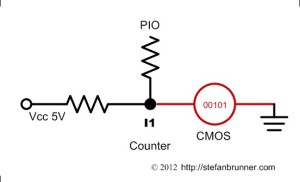
More interesting is that we can feed those inputs plain TTL or CMOS signals. The inputs look like the digital 5kΩ inputs on the Universal Inputs, but this just appears as such because the ports are pulled up, hence preset to 5V which is interpreted in negative logic as 0. I would like to mention it here, by studying the PCB, I suspect that those input can be configured as outputs as well. But I have not seen software support of that as of now.
The thresholds, as to be expected, are different from the Universal inputs in digital mode. The counter inputs are really digital inputs and expect a digital high/low signal but can also be operated with a resistive load because the interface is internally pulled to 5V. The thresholds are about 1V for logic 1 and 2V for logic 0 and should work nicely with TTL or CMOS levels. The resistive thresholds are 620Ω for logic 1 and 1.6kΩ for logic 0. In both cases, negative logic applies. (Universal interfaces use negative logic in 5kΩ mode but positive in 10V mode.) If negative logic makes your brain smoke, you can convert state in software with a NOT operator easily. The values are all listed in the table above together with the values for the digital Universal inputs so that they can be better compared.
There is no difference on whether the counter interface works in "counter" or digital mode. This again is a feature of software not hardware. The software simply counts one up everytime when the interface is pulled to 1 in counter mode. Be careful though, as logic 1 is also used to reset a counter input. In other words a short pulse of a logic 1, eg a switch pressed and released immediately, counts on up. A switch pressed and held on the other hand, holding logic state 1, resets the counter.
Ultrasonic Inputs
The Ultrasonic TX sensor is special in a way to all other fischertechnik sensors. It does not appear to deliver a resistance or a voltage level correlated to its distance. The sensor itself appears to communicate via digital messages with the processor. I do not have such a sensor so that I could sniff the protocol. But from probing around it looks to me that the sensor uses "bit banging" on a Universal input to transfer its message. If one would know that protocol it would be another very nice way to interface with the TX brick to other microcontrollers such a PIC, AVR, or Arduino. If I get my hands on one, I will sniff the protocol and publish it here.
I2C Input
I2C is a bus and allows you to connect over 1,000 input - or output - devices. I2C firmware and software support is new with the TX brick and was only introduced summer of 2012. There are no native fischertechnik sensors at this time using it. However, many users started experimenting with it and developing drivers. I2C sensors are usually single SMD chips which might only cost pennies. From a software perspective, however, they might be quiet complex, and may require the development of custom drivers. You can connect sensors like, precise temperature, pressure, compass, gyroscope, acceleration, precision color, distance, and even complex devices such as card readers. I will update this page as soon as a I have a chance to play around with it.
You need to download the RoboPro 3.1.3 or higher update from fischertechnik's Downloads page and install firmware 1.30 or higher on the TX brick.